gemellocattivo.com

Which means "Evil Twin". Lets see your projects where you change boring into fun or create the fun from scratch.
It is currently Sat Feb 21, 2026 12:35 pm

All times are UTC - 5 hours [ DST ]


Post new topic Reply to topic  [ 2801 posts ]  Go to page Previous  1 ... 274, 275, 276, 277, 278, 279, 280, 281  Next
Author Message
PostPosted: Sat Dec 06, 2025 11:56 pm 
Offline

Joined: Thu Jan 01, 2015 6:47 pm
Posts: 4759
Toe set. I pondered what to set it to thinking more toe-in should help with the self-centering but it tends to make the steering feel slow from what I read.....so I settled on 1/4"@ 48in which I think is about 0.083"@16" and and the factory spec is 0.06"-0.10" so about nominal and just see how it drives before trying more.

I also have a plan percolating in my brain involving torsion spring on the column to to force it to center if self-centering remains an issue.....but one way or another I expect to win this battle.

Then on to pedals I made it pretty compact which really didn't leave quite enough room and I had to cut the adjusting rods on the masters leaving like no adjustment. Then last year when I wanted to drop the pedals so my feet would clear the bulky EPS I had to add spacers and not knowing exactly what I wanted I just used washes equaling about 3/16"
Attachment:
20251206_141515.jpg
20251206_141515.jpg [ 2.99 MiB | Viewed 836 times ]


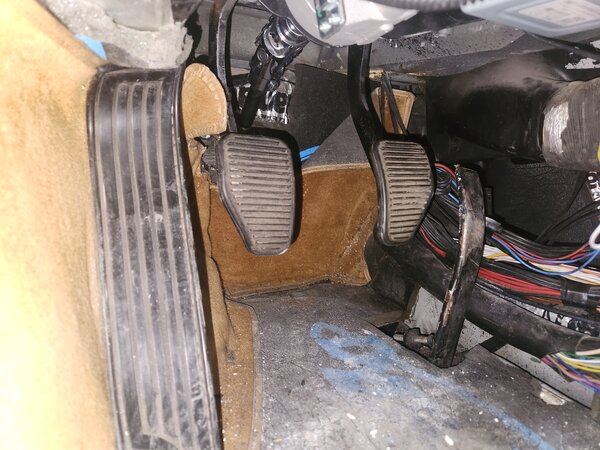
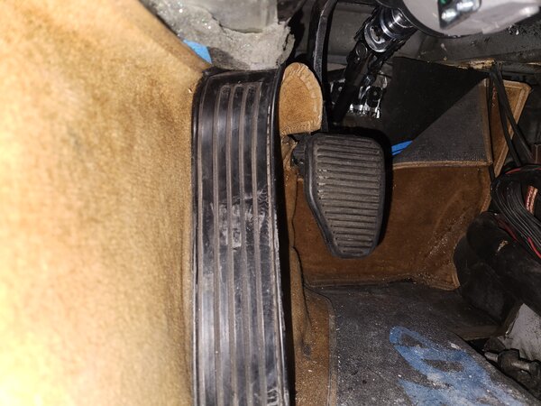
and that left the pedals here.....a little hard to see but the clutch is about an inch below the dead-pedal and the brake not as low but maybe 1/2" below the throttle all of which seems less than ideal.
Attachment:
20251206_143518.jpg
20251206_143518.jpg [ 2.89 MiB | Viewed 836 times ]


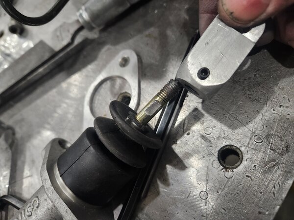
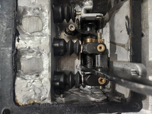
I do want to have some adjustment available so rather than red loctite replacing the jam nut that no longer fits I added a set screw to lock the mastercylinder rod position. No spacers puts it here with everything too high
Attachment:
20251206_170903.jpg
20251206_170903.jpg [ 3.3 MiB | Viewed 836 times ]


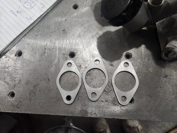
So I made 1/8" spacers to replace the 3/16" washers.
Attachment:
20251206_153746.jpg
20251206_153746.jpg [ 3.86 MiB | Viewed 836 times ]


The pedal ratio is about 6:1 so that should drop everything about 5/8" and that set the clutch a little low but now I can adjust it and I set it maybe 3/16 below the dead-pedal so my foot isn't quite touching it resting on the dead-pedal which seems right.
Attachment:
20251206_205722.jpg
20251206_205722.jpg [ 2.72 MiB | Viewed 836 times ]


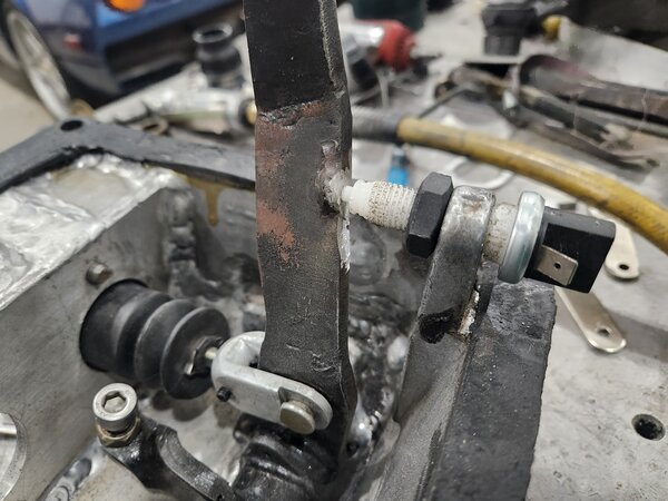
But that meant I had to adjust the clutch switch and that meant it hit the new EPS bracket. I know I don't want the pedal any higher than it is so I drove the switch full in and cut the tab I had welded to the pedal until it no longer held the pedal down and called it good. That leaves the switch about full compressed so it will still work if I decide to drop the pedal a bit more.
Attachment:
20251206_210247.jpg
20251206_210247.jpg [ 3.41 MiB | Viewed 836 times ]


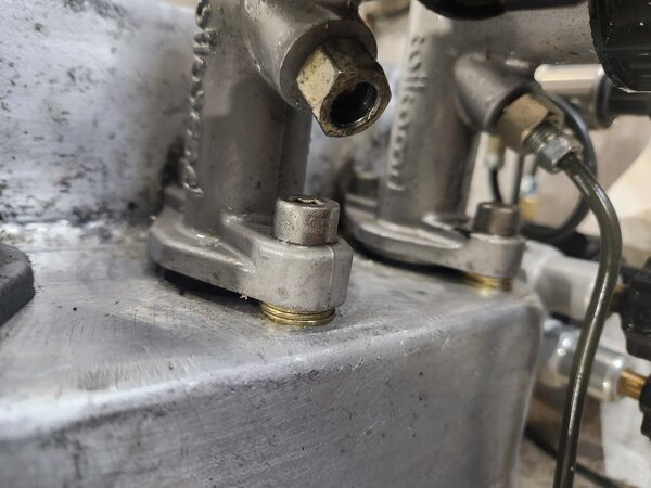
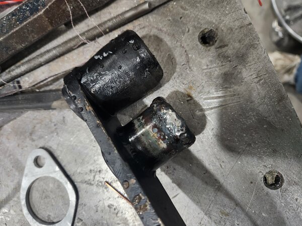
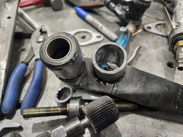
Then the brakes. I didn't do the best just on the balance bar. The rear master push rod sits nice and straight but the front master push rod was a bit angled.
Attachment:
20251206_172112.jpg
20251206_172112.jpg [ 3.52 MiB | Viewed 836 times ]


So I did what I do and welded almost a 1/4" of metal on
Attachment:
20251206_191520.jpg
20251206_191520.jpg [ 3.47 MiB | Viewed 836 times ]


then cleaned it up in the mill and also cleaned up the main pivot, I ground the original mechanism off and it just wasn't that neat.
Attachment:
20251206_195555.jpg
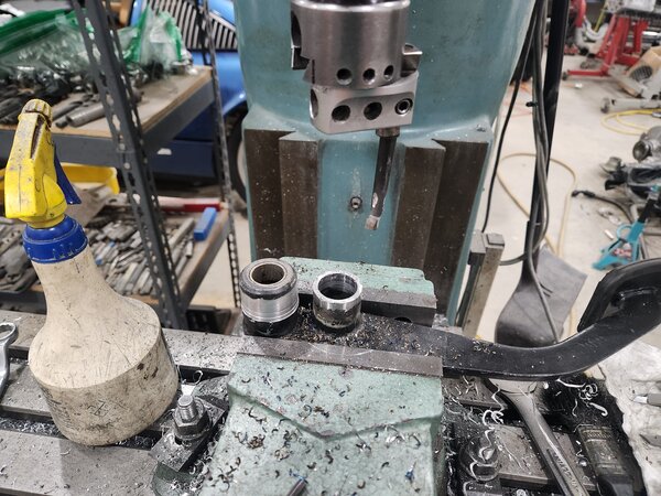
20251206_195555.jpg [ 3.84 MiB | Viewed 836 times ]


Then polished the bore so the balance bar bearing moves smoothly
Attachment:
20251206_202637.jpg
20251206_202637.jpg [ 3.3 MiB | Viewed 836 times ]


Then paint and call it a night. Tomorrow I'll get it all reassembled, the brakes bled, then power up the ECU to I can read the brake pressures and make sure the balance bar is correct with the new 5/8 rear master replacing the 0.70". Hopefully all that will be done before the arrival of a 24lb 318 bwm flywheel that is wishing to be be WAY lighter...I think I heard ice racer? but it will require my attention.


Top
 Profile Send private message  
 
PostPosted: Mon Dec 08, 2025 11:33 am 
Offline

Joined: Thu Jan 01, 2015 6:47 pm
Posts: 4759
I screwed around with the pedal for a bit….I think given the travel on the brake pedal and the desire to heel/toe it wants to sit at or slightly above the throttle position. …but that puts it like ¾” height then the clutch if I leave the clutch at or below the dead-pedal.  It looks wrong but I can’t think of a reason why its not ok?.  It was easier when nothing was adjustable.

I did some force balance math and set the balance bar but after getting everything installed it wasn’t even close to right and was a real bugger to adjust in the car.  I’m still not sure what I did wrong with the math but its close now, I wanted 80% I have 77% but I want to play with the numbers a bit more to see is 80 was “right” just because that is what the .625/.700 masters gave me or if that is what I really want before I crawl back under the dash

Also, there is a leak….I can feel the pedal sinking.  It looks like one of the fittings on the line going from the rear master to the 1st proportioning valve is weeping so I’ll start there.

And I can now only install 3 of the 4 bolts securing the pedal box…..I welded the steering bracket mount about 1/16” too far forward…Doh!...but its on the clutch side so doesn’t do much, I think I’ll ignore that.

Speaking of stuff to ignore, the steering has a little “pop” now near center.  It wasn’t there when I was testing and working but now that its aligned and the center position set it is.  The center piece in the double ujoint loads up and pops slightly…..its a pretty small steering wheel movement so not unsafe I don’t think but I don’t love it.  I’m pretty sure it’s the “w” brackets just not holding the column in place…..but I really want to be done with this….I’ll think about it. ….I think I found my salvation in a farm PTO joint:
Attachment:
high angle Ujoint.png
high angle Ujoint.png [ 131.72 KiB | Viewed 799 times ]


Its got some extra bits that prevent the center yoke from ever misaligning and no pop and should act like a single ujoint with no additional support required.  Perfect!  The problem is  I don’t find anything similar anywhere else….. so I think that means I should probably make one.  


Top
 Profile Send private message  
 
PostPosted: Mon Dec 08, 2025 11:46 am 
Offline

Joined: Thu Jan 01, 2015 6:47 pm
Posts: 4759
I ordered one of these too
Attachment:
double CV.png
double CV.png [ 185.89 KiB | Viewed 799 times ]

​​​​​​​

A GM double CV replacement for $55 to look at.


Top
 Profile Send private message  
 
PostPosted: Wed Dec 10, 2025 2:43 pm 
Offline

Joined: Sat Mar 26, 2022 1:39 pm
Posts: 164
All very cool.

If the clutch or brake switches give you any more hassle, remember that you can get banjo bolts that have an integrated pressure switch - popular for motorcycle use. We used one on my wife's Monster 620 clutch - the pressures there are so much lower than brake that I had doubts that it would work, but there was never an issue.


Top
 Profile Send private message  
 
PostPosted: Wed Dec 10, 2025 8:55 pm 
Offline

Joined: Thu Jan 01, 2015 6:47 pm
Posts: 4759
Syscrush wrote:
All very cool.

If the clutch or brake switches give you any more hassle, remember that you can get banjo bolts that have an integrated pressure switch - popular for motorcycle use. We used one on my wife's Monster 620 clutch - the pressures there are so much lower than brake that I had doubts that it would work, but there was never an issue.


I hadn't really thought about a pressure switch but its a fine idea if the current path end up causing problems

Speaking of problems the new double u-joint arrived (I didn't want to destroy the one that is installed and its only $25). my first thought was wait until Saturday and see if the GM double CV does what I want before touching it so I can send it back but while looking at it I had a though on a better/easier/cheaper and perhaps patentable way to build the high angle tractor PTO like setup and kind of want to see if it works and if it does it drops in with almost no work...so its apart and waiting for a few more bits from amazon.
Attachment:
20251210_193153.jpg
20251210_193153.jpg [ 5.56 MiB | Viewed 740 times ]


Top
 Profile Send private message  
 
PostPosted: Thu Dec 11, 2025 11:23 pm 
Offline

Joined: Thu Jan 01, 2015 6:47 pm
Posts: 4759
About an hour after I posted yesterday I realized the reason my new design reduced the problems to 0 is because it reduced the forces to 0 and with that the effectiveness to 0 so it was a pretty worthless concept. So... since I already took it apart making it mine and I decided to proceed with a basic double cardan as found on off-road driveshafts. They use a ball joint in the middle to keep the shafts aligned...I'm pretty sure I can get the 45deg I need.

Attachment:
double cardan.JPG
double cardan.JPG [ 62.79 KiB | Viewed 699 times ]


Step 1 is make room in the middle for the ball joint
Attachment:
20251211_180109.jpg
20251211_180109.jpg [ 3.58 MiB | Viewed 697 times ]

Attachment:
20251211_191143.jpg
20251211_191143.jpg [ 3.31 MiB | Viewed 697 times ]

Attachment:
20251211_195749.jpg
20251211_195749.jpg [ 3.59 MiB | Viewed 697 times ]

Attachment:
20251211_214011.jpg
20251211_214011.jpg [ 4.46 MiB | Viewed 697 times ]


Top
 Profile Send private message  
 
PostPosted: Sat Dec 13, 2025 11:32 pm 
Offline

Joined: Thu Jan 01, 2015 6:47 pm
Posts: 4759
The GM double CV arrived but was not helpful as it turns out its a fixed angle, about 70deg =/-2deg. I suspect the angle could be changed but I didn't open it to find out.
Attachment:
20251213_141905.jpg
20251213_141905.jpg [ 3.47 MiB | Viewed 645 times ]


So back to the 1st plan. The yokes needed straps added
Attachment:
20251213_162137.jpg
20251213_162137.jpg [ 3.34 MiB | Viewed 645 times ]

Attachment:
20251213_163057.jpg
20251213_163057.jpg [ 3.72 MiB | Viewed 645 times ]


Then find the center and weld a sleeve to 1
Attachment:
20251213_165059.jpg
20251213_165059.jpg [ 3.56 MiB | Viewed 645 times ]

Attachment:
20251213_173326.jpg
20251213_173326.jpg [ 2.82 MiB | Viewed 645 times ]


and a ball to the other
Attachment:
20251213_184820.jpg
20251213_184820.jpg [ 3.19 MiB | Viewed 645 times ]


and its a self aligning double cardan, which is a CV joint btw because the 2 joints end up equal and opposite resulting in a smooth constant velocity output so in theory much better than a single high angle ujoint.
Attachment:
20251213_193441.jpg
20251213_193441.jpg [ 3.71 MiB | Viewed 645 times ]


When I pulled apart everything on the car I discovered the set screw securing the adapter shaft between the ujoint and the EPS had come loose which let the shaft rock a bit...and that is almost certainly why the steering was tight until it wasn't. I converted that to a pitch bolt and the modified ujoint shouldn't be putting cyclic side loads on it anymore so there should be no repeat.
Attachment:
20251213_205031.jpg
20251213_205031.jpg [ 3.34 MiB | Viewed 645 times ]

Attachment:
20251213_212951.jpg
20251213_212951.jpg [ 3.7 MiB | Viewed 645 times ]


Then paint and see if it works tomorrow.
Attachment:
20251213_214654.jpg
20251213_214654.jpg [ 3.28 MiB | Viewed 645 times ]


Top
 Profile Send private message  
 
PostPosted: Sun Dec 14, 2025 9:15 pm 
Offline

Joined: Thu Jan 01, 2015 6:47 pm
Posts: 4759
Everything went together fine and the popping is gone...but it wasn't right either. Head under the dash and I could see the ujoint yokes moving sideways??? I grabbed the 1st joint to look at and yup, the cheap chinese ujoints have a clear design flaw I missed. They have rubber grease seals on the shaft which is a nice touch but they are also using them to remove side lash so if you push, the joint move in directions it shouldn't
Attachment:
20251214_135155.jpg
20251214_135155.jpg [ 3.79 MiB | Viewed 596 times ]


This was an "I need a break to be less angry" before continuing moment. Rip it apart again, rubber seals out. Spot face where the bearing retaining screws sit and drive the bearings in to remove the side lash. I
Attachment:
20251214_151003.jpg
20251214_151003.jpg [ 3.09 MiB | Viewed 596 times ]

Attachment:
20251214_154634.jpg
20251214_154634.jpg [ 3.03 MiB | Viewed 596 times ]


also turned the adapter on the rack about 45 degrees because the ujoints were sitting in their least stable orientation when the wheel was straight which seemed less than ideal. Column back together...still a little lash...rip it apart and cut a bit deeper, back togethers....FINALLY! its right I think.

I still need to put the EPS control box and wiring back but enough for today. Tomorrow I button that up and then fix the leaking brake line and reinstall the pedals. I'm going to try pre loading the impossible bolt, I slipped it in place with a little piece of tape to hold it, hopefully that works...or there will only be 3 bolts.
Attachment:
20251214_190801.jpg
20251214_190801.jpg [ 3.33 MiB | Viewed 596 times ]


Top
 Profile Send private message  
 
PostPosted: Mon Dec 15, 2025 11:00 pm 
Offline

Joined: Thu Jan 01, 2015 6:47 pm
Posts: 4759
I went back out to the shop and trying the steering ...and it still works fine...2 days in a row. Crazy!

so controller and wiring back in and that's all fine.

Quick run to the auto parts store for a new line to replace the leaker. Then inspect everything and actually found the source of the leak:
Attachment:
20251215_195403.jpg
20251215_195403.jpg [ 3.24 MiB | Viewed 557 times ]


Not sure how that happened but I had a spare. New line in. Pedal box in and I'm almost back to where I was 2 weekends ago...just need to bleed the brakes tomorrow and I'll be there. Then I need to I need to move some stuff around...maybe skootch the car over a few feet to make room for my son to do his ducati track prep adventure and I'll go back to engine work....which I'm sure means actually more bike time than car time for me until winter break ends.

I'll share this because it kind of broke my brain. The bike needs the lower fairing to be a catch pan to comply with the rules but that is where the muffler is on the V2 so it needs new exhaust. The primaries are 2 3/8"!
Attachment:
20251215_191518.jpg
20251215_191518.jpg [ 3.97 MiB | Viewed 557 times ]


I don't think I've ever seen a header pipe that big. Its 478cc/cly vs my engine that is 458, but I only run 1 5/8" primaries, then 2" 1st collector and then 2 3/8" 2nd collector (6>2>1). There is no way my software would tell me that is the right thing to do so now I'm not exactly sure how to guide/help him designing the new system, I've just never seen anything like this ..oh, then the single muffler outlet is tiny...1 1/2"or maybe 1 3/4" (didn't measure) I don't understand that either.....its almost like there is no primary and the collector only? I just don't understand.


Top
 Profile Send private message  
 
PostPosted: Tue Dec 16, 2025 8:02 pm 
Offline

Joined: Thu Jan 01, 2015 6:47 pm
Posts: 4759
Brakes are sorted and the car moved out of the way for the bike. Still a lot to clean up and the BMW flywheel is coming for actual machining Saturday I think and I don't think he's ever run a mill. I need to get the valves ordered hopefully tomorrow so I have a shot at finishing the heads over the holiday.
Attachment:
20251216_183301.jpg
20251216_183301.jpg [ 2.91 MiB | Viewed 506 times ]


Top
 Profile Send private message  
 
Display posts from previous:  Sort by  
Post new topic Reply to topic  [ 2801 posts ]  Go to page Previous  1 ... 274, 275, 276, 277, 278, 279, 280, 281  Next

All times are UTC - 5 hours [ DST ]


Who is online

Users browsing this forum: No registered users and 52 guests


You cannot post new topics in this forum
You cannot reply to topics in this forum
You cannot edit your posts in this forum
You cannot delete your posts in this forum
You cannot post attachments in this forum

Jump to:  
Powered by phpBB® Forum Software © phpBB Group